

If you have access to a CNC router then isolation milling is great option for single sided PCP boards. This approach doesn’t need toxic etching chemicals and has the added bonus of pre-drilled holes for your component. We recently used this approach to prototype our Ephemeral Clock.
PCB Design
When you designing your board for CNC milling you have to take a couple of things into consideration. While this process can give you very thin traces, it’s better to opt for wider than what you would use on a regular printed PCB or you run the risk of scratching or otherwise damaging the thin copper traces. The slightly raised and rough edges of the etch means this is more likely to happen than with a regular printed PCB. If the resolution is poor on your mill or for whatever reason the accuracy is off, thick traces will also give you the best chance of having a usable board. Go for the biggest pad size possible for components and header pins, soldering will be easier and it avoids having the copper pads peel off. Pads for unconnected pins on ICs are particularly susceptible to this.
Below is the guidelines for spacing your traces from the IPC-2221 (Generic Standard on Printed Board Design). B2 will likely be the most relevant column for your design, with uncoated external conductors below 3050m elevation. You’ll need to take this into consideration both designing your board and when choosing the width of the isolation milling latter on.

Getting Started with PCB GCODE
The pcb-gcode user language program for Eagle that makes it easy to export CNC ready gcode from your design.
Download the latest version of the ULP and unzip into your eagle application or project folder.
From the Eagle control panel select Options > Directories. Under User Language Programs you will need to browse to and select the the pcbgcode folder.

Now inside your brd file, select the Run ULP from the menu bar. Navigate to pcb-gcode-setup.ulp and run.
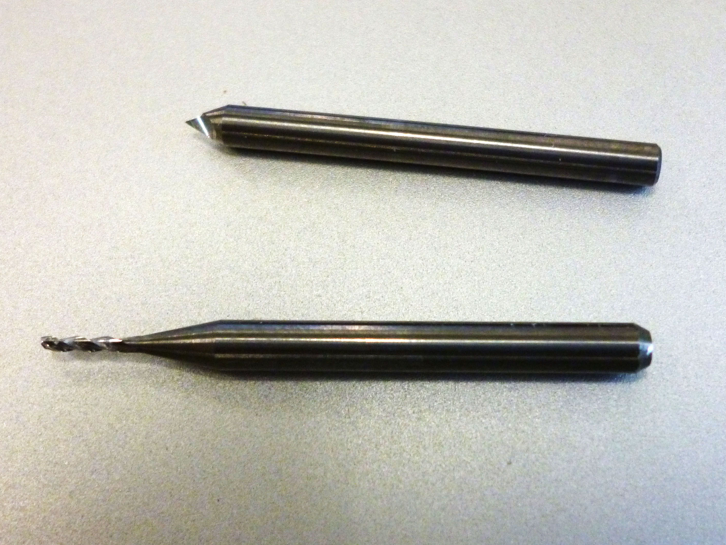
We just want to remove enough copper from the board to create a safe amount of isolation between all our traces and pads, otherwise it will take the CNC machine too long to remove all unused material on the pcb. Judging the safe amount of isolation will depend on your project and what sort of voltages you are using. You can set this under Maximum in the Generation Options, along with the tool size your using and the minimum isolation. We used a .15 mm V etching bit for the milling and 2.5 mm drill bit for through holes. You don’t need to etch any deeper than .10mm, or you will be just milling through the glass fibbers in your board which makes dangerous airborne particles and dulls the etching bit.
PCB geode gives you the option to spot drill holes, this means small depressions will be made during the etching phase before you swap over the tool for drilling. Unless you are going to hand drill the holes this step isn’t necessary and can make a mess if you are off center after you swap the drill piece.
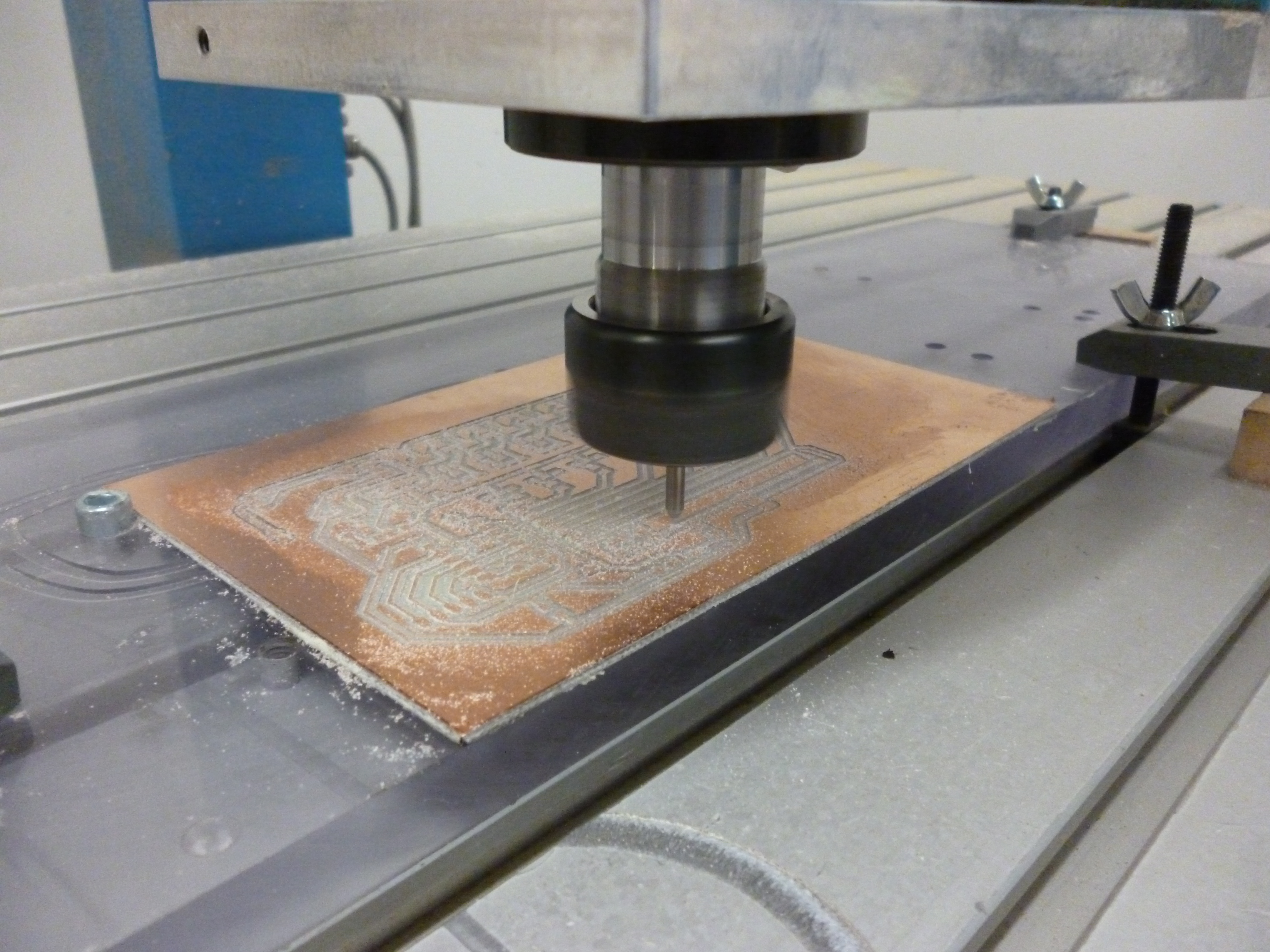
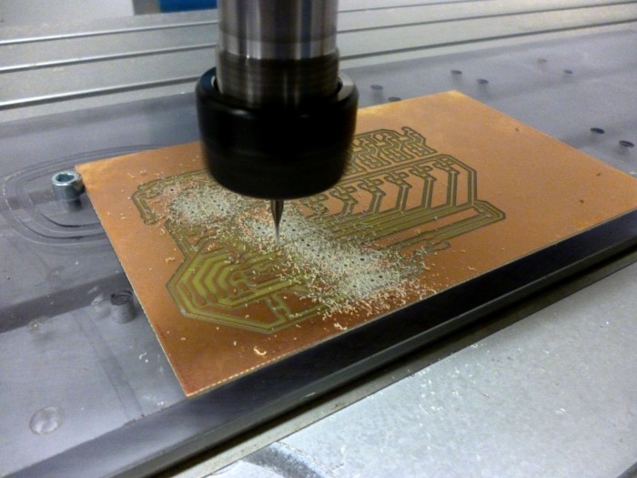
Milling
1200 RPM was sufficient for engraving. Your copier board needs to be laid on an a very flat surface, we used a thick piece of Plexiglass. This will also protect the mill surface if you make a mistake and end up drilling below your 0 point on the Z axis. Since we are removing such thin layer it’s essential that PCB is completely flat, or parts of the pcb won’t be milled or milled too deep like the image below. Double sided tape works well for holding the PCB in place. We used double sided tape to keep the board in place.
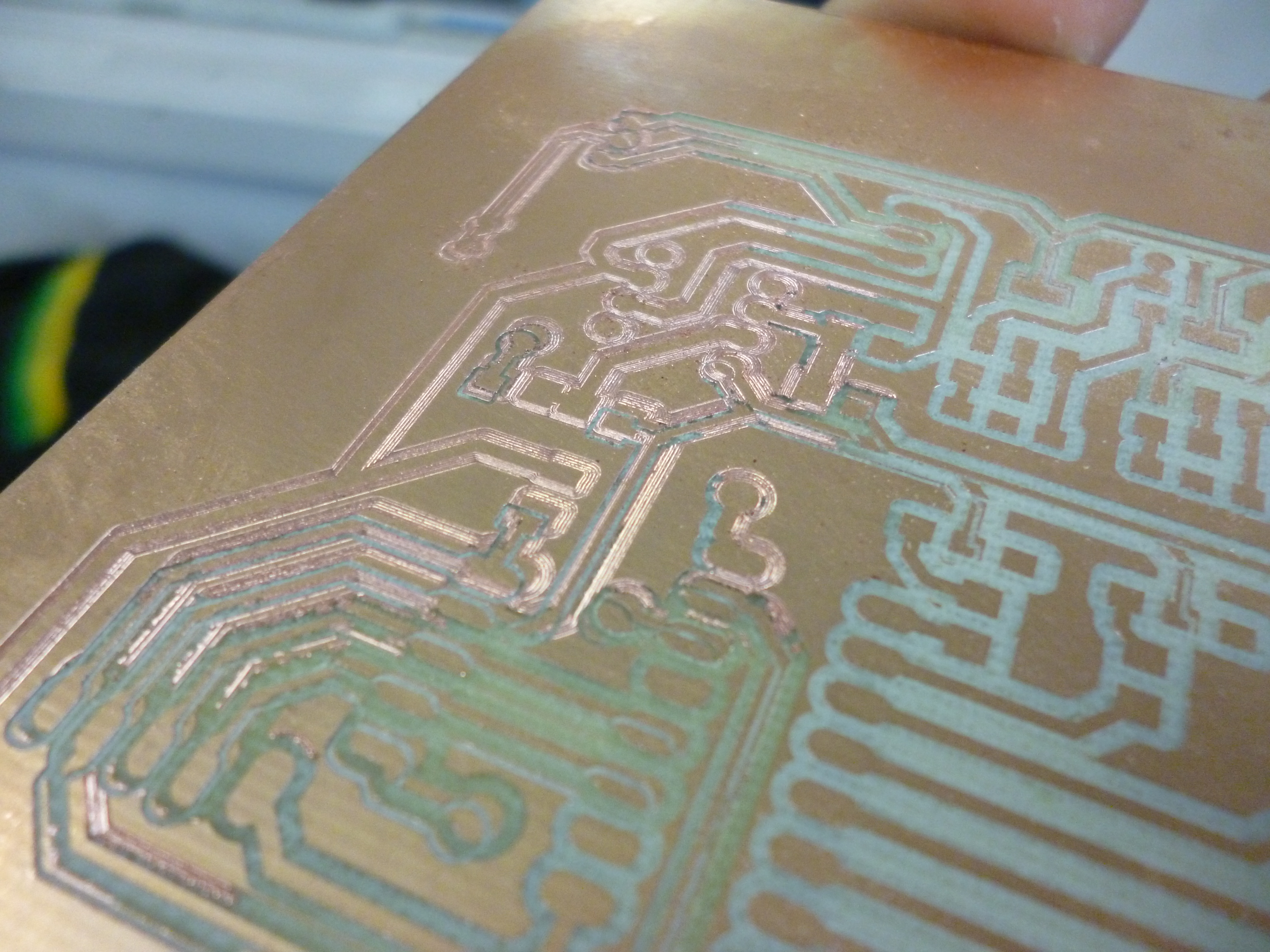
After you are finishing simply use some steal wool to clean of any oxide and rough edges and you are ready for soldering.